
I've used a Hamtronics R139 WX Satellite receiver for receiving weather satellite images from the NOAA polar orbiting satellites for a number of years. My system is setup to automatically receive images over the air from the satellites and to publish them to a web site.
A problem I've run into with this setup is that the Hamtronics R139 does not have an interface to allow a computer to control the channel it is tuned to, so I've added a computer control circuit to my R139.
The Hamtronics R139 WX FAX Receiver is a 5 channel crystal controlled receiver specifically intended for reception of the polar orbiting weather satellites that broadcast on the 137 MHz weather band. The receiver has a wideband IF that allows for reception of the wideband FM signal from the satellites. The received audio from the receiver is passed to a computer sound card where a program such as WxToImg is used to decode it to an image.
The R139 can scan the 5 channels and automatically stop on an active channel. This works well provided one has a strong signal. If the signal is weak or subject to fading the squelch will close and the scan will resume during the satellite pass which results in a truncated satellite image. For reception of the satellite pass horizon to horizon manual selection of the received channel and running with open squelch is needed.
The channel selection circuitry of the R139 is shown in the schematic below.
Switch S1 controls the channel selection of the R139. When it is in the AUTO position, the radio scans based on the COS input from the demodulator section. When in MAN mode, the radio does not scan and can be stepped to the next channel in the sequence by switching S1 to the STEP position. This grounds the input of U4B and enables clocking of the 4017 Ring Conter.
The outputs of 4017 (Q0-Q4) drive indicator LEDs and enable one of the crystal oscillators in the local oscillator section of the receiver.
The basic idea of the computer control modification is to allow the computer to determine the currently tuned channel by looking at the outputs of the 4017 Ring Counter and to step the receiver by grounding the STEP input at U4-B.
Using a serial port in a bit bang mode to do this seemed like a simple low cost approach. In bit bang use of a serial port, there are 4 signals that can be used for input, and 2 for output. For the R139 modification I needed 3 input signals to encode the currently selected channel and 1 output signal to control stepping the channel selection line.
Using a serial port made for simple programming and hardware, but was not ideal for interfacing to a PC as most PC's these days are somewhat limited on the number of serial ports they provide. USB connection is a more convenient way to interface to a computer, so I decided to use a DLP-USB232M USB to Serial module. The DLP-USB232M makes it very simple to convert a serial port based design to USB as drivers for it are freely available.
The schematic below shows the computer control circuit.

The circuit is divided into two sections, the radio side of the circuit that determines the currently selected channel and allows for strobing of the STEP line and the computer interface side of the circuit. The radio side of the circuit draws its power from the radio and the computer side of the circuit draws its power from the USB bus via the DLP-USB232M module. The two sides of the circuit are coupled via an optocoupler (OK1 - PS2501-4).
Power for the radio side of the interface is provided by fixed regulator IC4 or alternatively via variable regulator IC3 with R4 and R5. (Only one of these is populated on the circuit board). The logic on the radio side is 74LS CMOS running at a supply voltage of 2.5 volts. The 2.5 volt supply is needed because the outputs of the 4017 are directly driving LEDs and when high, they are only at about 2 volts, so logic that will interpret 2 volts as high is needed.
To determine the currently selected channel, the 4017 ring counter outputs are snooped by the radio side of the interface board. When a channel is selected, the appropriate output of the 4017 is driven high (2 volts or so). The outputs of the ring counter are fed to IC2, a 74LS04 quad inverter, and then fed to a IC1, a 74LS148 8 to 3 line encoder. The outputs of the encoder are fed to optoisolators (OK1). The optoisolators are connected to the DCD, DSR, and CTS inputs of the DLP-USB232M serial to USB module to make the signals available to the computer.
Computer changing of the selected channel is accomplished by having the software strobe the RTS line. This turns on the optoisolator OK1D grounding the STEP line on pin 5 of the 4001 on the R139.
All of the signals needed from the R139 for the computer control board are present on the pins of the socketed 4001 and 4017 chips on the R139 board. Removing the socketed chips from the R139 allows the computer control board be installed by mounting it on top of a stack of DIP IC sockets plugged into the sockets on the R139 board.
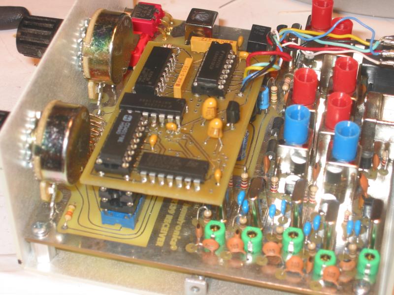
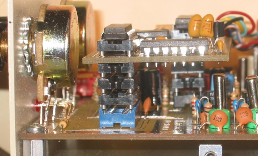
The photos above shows the computer control board installed on a stack of three DIP sockets to raise the board above the components above it. The 4011 and 4017 chips from the R139 board have been relocated to sockets on the control board board. The connection to the DLP-USB232M module is brought out to an 8 pin mic connector I added to the back of the R139 case.
The connection to the computer is via a DLP-USB232M serial to interface mounted in a small project box with an 8 pin connector to mate to the back of the R139 receiver. The schematic for the DLP-USB232M circuit is shown below.
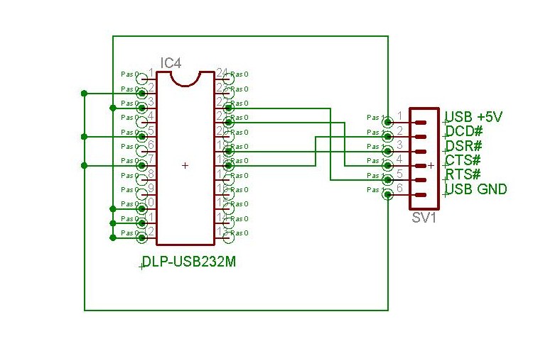
There's really nothing to this circuit, other than to connect the signals from the 8 pin connector to the appropriate pins on the DLP module and to configure the DLP module to be bus powered.
Currently I've got a simple Java program I use to control the radio. It reads the status bits of the serial port to determine the currently tuned channel, and strobes the RTS line to advance to the next channel. I've got it setup to tune the radio based on the time of day, 99% of the time this has it tuned to the correct channel for a satellite pass. In the future I'd like to modify it to work with the WxToImg program so WxToImg can tune it, or do have it hook into a Predict server to determine the currently visible satellite.
Comments to: Bill Tracey (kd5tfd@ewjt.com)
Last Updated: 29 August 2005
Copyright © Bill Tracey 2005